Starting the Electrical Foundation of my 4Runner
As a fair warning to readers, this guide is not meant as a step by step instruction replacement. I sincerely recommend consulting each product’s installation guide as a source of definitive information. Please consider this article as more of a personal review and collection of tips for these products.
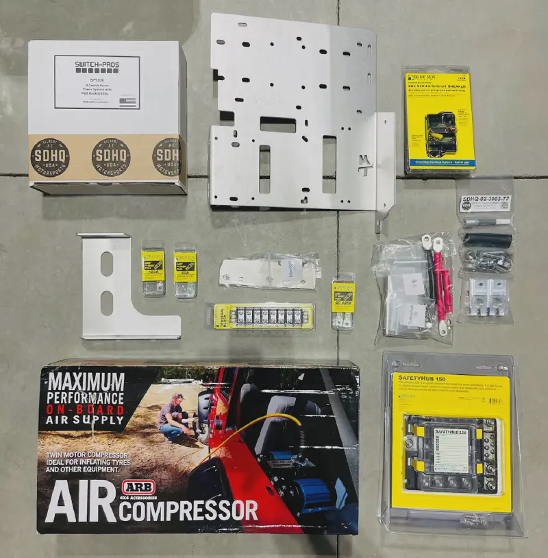
Foundation Components
I have grand plans for years of adventures and a long list of modifications for my 2021 Toyota 4Runner. It remains unknown if I will fulfill all my aspirations but in order to achieve any of them I needed a solid electrical foundation to efficiently springboard future modifications. I have read many stories of people installing modification after modification and their engine compartment ended up being an inevitable spaghetti bowl of cables. Not only is this clutter hard to diagnose and fix if the need arises it can also be dangerous since it isn’t isolated away from your vehicle’s core electrical system. This is when fuse blocks, bus bars, and solid state switches into play.
Fuse Block
Probably the most affordable and beneficial thing to add to your vehicle when accommodating a variety of electrical modifications is a fuse block. This little device basically acts like the fuse panel in your home. It protects from electrical overcurrent along each isolated circuit. Instead of starting a fire in your vehicle engine compartment you might instead just have a bad fuse you replace for a few dollars or less. A universal best practice is that the capacity should reflect approximately 125% of your overall calculated load of whatever you intend to run through it. For a 12 amp light bar it would be ideal to use a fuse with a rating of 15 amps. Some really high draw modifications like a winch wouldn’t necessarily go through a fuse block but I run my 80 amp (40A x 2) twin compressor through it. The reasoning behind this is that a winch already has a fuse installed inline to the cable that you hook up directly to the battery. So it accomplishes the same safety feature, albeit in a more cable cluttered manner. But its also a balancing act to be able to include the majority of your accessories while a few outliers remain, which is perfect fine. For my own purposes I went with a Blue Sea SafetyHub 150, which was part of the package that I purchased from SD Offroad.
Solid State Switch
As the second part of the solution, the solid state switch, is much more advanced and quite a bit more expensive. The purpose of a switch is to consolidate all your devices into a single universal panel. Rather than trying to fit a switch for your light bar, ditch lights, compressor, side lights, rock lights, and whatever else onto your dashboard, you can instead just combine them all into a single sleek panel. The most popular products for this come from either Switch Pros or sPOD. There are certainly ways to achieve the same end result with a do-it-yourself approach but it requires quite a bit more electrical design and fabrication. If you are a fan of electronics and tinkering it is certainly worth a look. Although I find myself tinkering more and more these days I decided to go with a Switch Pros SP-9100 to save some time and provide a stable and safe foundation for my vehicle. The mad scientist stuff1 will be coming up soon enough! This model had some great community feedback and the feature set suited my needs perfectly. Some considerations you might take when choosing a solid state switch model is to simply map out your anticipated modifications in a list and their amperage draw. Be aware that some electrical needs won’t to be switched and shouldn’t be a part of your anticipate design. A fridge will most often be plugged into your secondary power source and won’t generally be switched on and off like a light bar would. Another example I previously mentioned would be the winch since the amperage draw is so high it would not be feasible to route it through an incorporated solid state switch that had a maximum draw limit of 35 amps.
Onboard Air Compressor
Another foundational modification to consider in this great initial project is an off-roading oriented glamping modification: the onboard air compressor. There are cheaper ways to inflate your tires. I have actually owned a little mobile air compressor for several years that has served me well. The only problem is that the little guy can only work for so long before overheating. This can be a major time sink for off-roading because you are inflating all four of your tires to suite your terrain and speed. To save time I found myself skipping airing down or airing up at locations where I probably should have done so just to avoid the long wait for my compact air compressor to work through all four tires. Lowering your tire air pressure isn’t just for tackling aggressive terrain. Mild dirt roads can be made smooth by taking a little air out of your tires from their paved highway levels of PSI. For the sake of efficiency I decided to go with a crazy fast ARB twin air compressor. This thing is a beast and inflates all four of my tires without a whisper of slowing down. Being mounted in the engine bay also saves a tiny bit of room in the back and prevents me from ever forgetting to bring it along.
Mount
To bring all three items together required a not so common vehicle bay mount. There are quite a few available in a wide variety of orientations and combinations, however, I didn’t see many on the market that could consolidate a fuse block, a solid state switch, and a large twin air compressor into a single platform. Also, the solid state switch mounting point needs to be vertical since if you mount a Switch Pros SP-9100 horizontally the warranty is actually voided. After some time looking around on various sites and forums I came across the SD Offroad Mount Tray. The product was a little new when I came across it and was only being sold from a guy’s Instagram account rather than a traditional website or storefront. This might be a little sketchy to some but I have been coming to enjoy little shops like this more and more. With the huge availability of 3D Printers and other fabrication tools it gives a person with a great idea the platform to publish that idea into the physical world. There are a few other shops I have plans to become a patron of in the future for their original ideas that were successfully implemented into great products. Regardless, this mount tray fit all my needs and past customers seemed to be pleased with the product so I reached out. After a few questions from Derek about my future plans and needs we decided on package and a price. Besides the mount he included the Blue Sea SafetyHub 150, 8 slot bus bar, circuit breaker, 3 fuses (125A, 2x40A), and the rest of the items needed to get everything connected. Prices on fuses, bus bars, and everything else were in line with market rates, if not just a little below.
Parts and Tools
- SD Offroad Mount Tray - Probably the best way to combine your Switch Pros, fuse block, and ARB Twin Compressor into a single package under your hood. Currently the only way to buy this is to send a message to Derek on Instagram.
- Switch Pros SP-9100 - The brains of the operation.
- ARB Twin Air Compressor 12V - Model number is CKMTA12. Most American auto DC voltage uses 12V whereas 24V is present in other countries.
- ARB Hose Coupling 0740112 - There a few types of this model floating around so make sure to get the correct one. In order to fit the ARB Twin Compressor it needs to be a 1/4 x 18 NPT male fitting.
- ARB Fitting Plug 0740113 - Pricy piece of plastic but it will keep your fancy new twin compressor dust free on the inside. This cap will fit both the 0740112 and 0740113 models of hose coupling. For the life of me I don’t understand why ARB simply doesn’t include this with the hose coupling itself.
- SDHQ Off Road SP-9100 Keypad Mount - (Optional) This replaces a section of your dashboard in order for the SP-9100 keypad to sit a bit more flush. It isn’t exactly flush but it looks a bit better. SDHQ recently started offering a mail in service where they modify your existing dashboard panel to fit the keypad.
- Crimp Battery Cable Ring Terminals 10-4 Gauge - Useful to have on hand if you are terminating cables that are outside the 22-10 gauge set I link later on. I used these to terminate the ARB compressor positive and negatives to avoid using the provided unnecessarily long wiring kit. You should consider purchasing a more robust hydraulic or impact crimper to handle these larger gauges.
- Crimping Tool for Heat Shrink Connectors - In retrospect, I would have actually gotten the crimper in the 8 or 11 piece package because the die is swappable with other crimper dies. This becomes really important if you have plans to add Baja Design lights since they use Weather Pack Connectors.
- Heat Gun - Critical to achieving water tight sealing on your cabling connections. This thing eats batteries like no one’s business. Maybe consider a corded version.
- Heat Shrink Tubing Kit - Make sure all the components you are buying is Marine Grade. You vehicle is exposed to a great deal of environmental variation and all this stuff needs to hold up. This Wirefy brand seems to be universally respected, even within the DIY Solar community.
- Heat Shrink Wire Connector Kit - I got the large 540 piece kit since I will be using it for my own future modifications and other electronics I setup around the house.
- Wire Strippers - Having decent wire strippers is critical for your sanity since this project requires a ton of wire stripping. If you plan on doing a lot more of your own electrical work in the future it would be helpful to upgrade to a more elegant stripper 😏 like the Klein 11063W.
- Anti-Seize Lubricant - Used on the bolts at the bottom of the support arm. They go into the wheel well and will be frequently exposed moisture and road salt.
- Threadlocker - I went with Loctite Blue 242 here because Red seemed like overkill. This is mainly used on the nuts that are on the bottom of the mount tray.
- Cabling Sleeving - (Optional) For the above and beyond person who wants to waste hours and hours for that extra ‘gram worthy slick setup. I used Teleios Black at 4mm. You might have to source this elsewhere if you wanted to sleeve the larger gauge cables in your setup.
- Dymo Label Maker - Labelling your cables makes it look both professional and also keeps everything organized. When you are working on something in months or years in the future you will know exactly what goes where.
- Heat Shrink Tube Labels - Many of the off-brand suppliers are good quality and are considerably cheaper than Dymo specific. Most of my labels were either 1/2" or 3/4".
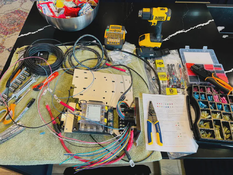
Assembling
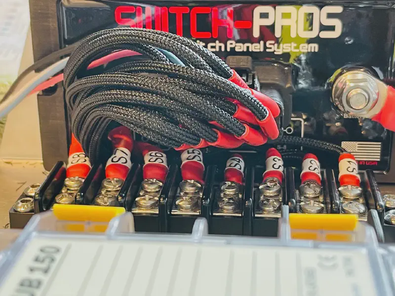
Wiring the Switch Pro while mounted
For your own sanity and the sanity of anyone you reside with it would be best to lay all components out on a flat work bench or kitchen table. Cabling and assembling everything in the engine bay would be a monumentally painful endeavor. I plopped my stuff down on the kitchen counter for a few weeks and spent some time here and there when I got the chance. However, if you have experience with wiring and aren’t adding any custom sleeving it would be rather easy to assemble it all in a few hours. The biggest time sink during my install was the custom sleeving, applying red heat shrink tubing, and labelling all sides of the cable terminations. In retrospect I would have forgone the custom sleeving but done everything else identically. The black nylon sleeves certainly gave a great look but for the time spent I don’t think it was worth it. My motivation was from this wizard that made it look like a high end custom gaming computer.
To kick off the installation and guide us for the rest of the installation is to realize there are simply 8 electrical switches on the Switch Pros SP-9100. Every action during the install is to provide an elegant platform to complete the electrical connection of those switches. The first action requires us to connect each of the 8 switches from the SP-9100 to an individual slot on the bus bar. As you can see in the above image the SP-9100 is vertically mounted very close to the bus bar. The connections on the SP-9100 exit out horizontally, which creates your first design problem you must creatively overcome. I didn’t want a larger curved loop of cables so I made all my connections in a rather tight circle back around to the bus bar. A great source of potential cable arrangements is to view the posts on the SD Offroad Mount Instagram page. There are a wide variety of approaches to taming this mane of cables into the bus bar.
Bus Bar
Using a bus bar for our 8 switches isn’t electrically helpful but it creates a semi-permanent and modular system for completing our electrical connections. The connection from the SP-9100 is intended to be semi-permanent and static while the other side of the bus bar connections are modular. This way you don’t have to fiddle with the SP-9100 side of the bus bar when future projects dictate different needs. You can simply disconnect the other side of the bus bar and move things as needed. This comes at a cost of introducing a point in your electrical system to environmental degradation and connection issues. If you already have a permanent system configuration planned out it would be much better to directly connect your devices directly to the SP-9100 and forego the bus bar entirely. Switch-Pros even advises this on their website2. But if you are like me and have a ever changing outlook on your modification endgame it is incredible helpful to have the modularity of a bus bar.
Labels for each Switch Pro connection
The current capacity for each of the 8 switches of the SP-9100 is outlined in the list below. Switches 1-4 are limited to 18A while 5-8 have a larger 35A capacity. These values are purely maximum and can be adjusted in the SP-9100 mobile application. As an example, on switch 1, my connected device is the trigger wire for my ARB twin air compressor and it is rated down to 5A. The trigger wire is basically an on/off switch for the compressor and doesn’t need any more current. There are many more features the SP-9100 can do such as strobe, 10% light output dimming, and a variety of trigger actions3. Another convenient thing about using the SP-9100 is that the fuses are built inline within the device. So you can connect all of your devices directly into the SP-9100 without those bulky inline fuses. The only catch is that if you exceed 85% of the switch load and you can’t move to a higher capacity switch they do recommend adding a relay or fuse inline4.
Switch Pros SP-9100 Wires
- Brown - Switch 1 - (18A)
- Red - Switch 2 - (18A)
- Orange - Switch 3 - (18A)
- Yellow - Switch 4 - (18A)
- Pink - T1 - (Trigger)
- Black - Ground
- White - LT - (Light Dimming Trigger)
- Blue - Ignition
- Green - Switch 5 - (35A) 2 Wires
- Blue - Switch 6 - (35A) 2 Wires
- Purple - Switch 7 - (35A) 2 Wires
- Grey - Switch 8 - (35A) 2 Wires
For the higher amperage switches from 5-8 you can simply twist both copper strands together before crimping down. Make sure you don’t cut the black, pink, white, or blue cables. These cables are connected elsewhere and shouldn’t be trimmed until you know the exact needed length.
Installation Preface
Based on the guide from SD Offroad there are several cycles of putting the mount tray in your engine bay and removing it for adjustments. While these steps seem useless when you could simply pop the tray in one go they are actually a measured approach to make the install easier. The incremental approach helps the installer make the required fitment adjustments as you go along while specific screws or support brackets are easily reachable rather than at an inverted right angle with only an inch of clearance. I was a bit pigheaded and did the install in many fewer steps and in the end I paid my time and frustration tax. Its almost as if guides are meant to make things easier. Somehow my logical reaction is to completely avoid the instructional guidelines since I know best. Spoiler: I don’t.
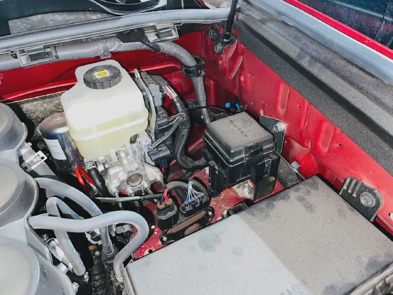
OEM engine bay
Pre-Installation
Placement of the mount tray is pretty straight forward. My 2021 model had a few differences from the SD Offroad Mount installation guide but it wasn’t anything major. The only physical modification required before being able to get the tray in was to file off the retention tab of the steel plate to the right of the smaller RELAY & FUSE black box. Getting the retention tab out of the way opens up the use of a required threaded mounting hole for the tray support bracket.
Another preparation required before getting the tray installed would be to run the longer SP-9100 wires from the engine bay into the vehicle cab. This would be the pink, white, and blue wires. Disconnecting the wire harness from the SP-9100 would be appropriate here in order to get the most flexibility. I chose to puncture through the circular black rubber grommet in order to get these wires through, however, there are probably more appropriate conduits available. I certainly recommend researching this further and I consider it one of my oversights when performing this installation. The grommet was actually a pain to work with since any pressure from either direction would unseat the perimeter flange lip. Getting it back to a sealed state was a major pain due to the tight space around the grommet on both the engine compartment and cabin sides. However, it is critical to get the grommet back in place as it is the only mechanism to stop water and anything else from entering the cabin for that rather large hole.
Installation
After these items are taken care of you can loosely install the tray. Make sure to coat the bottom leg support bolts with anti-seize lubricant since they exit directly within the wheel well. They will be directly exposed to the harshest conditions you’ll be driving in. The bolts also might be a bit firm when screwing them in for the first time but that is just the OEM plugs being forced out. When checking hood clearance for the tray it is a bit tricky to see if things are bashing into each other. I stuck my phone into the engine bay while taking a video and closing the hood in order to get an idea of physical clearance. My 2021 model has a fire retardant fabric on the bottom of the hood and is slightly pressed against by the vertical ARB compressor coupling. There are ways to modify the angle of the coupling mount on the ARB but I didn’t think it was necessary with my minimal amount of contact. I have seen other kinds of couplings, such as pure brass right angle hardware that might better fit in your intended setup.
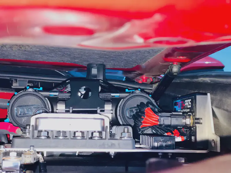
Checking clearance for the hood
One last point involves skipping the rivet installation for the mount tray. While the SD Offroad installation includes this as a step during installation I found that the mount tray was stable enough with all the other hardware to not warrant putting in the rivet. This might change after the physical stress of traversing over several thousand miles of washboard roads over the next year or two but I will monitor it closely, as I do with all my other bolted on modifications. Another reason for not installing the rivet was just avoiding an extra bolt to take out in case any access to the engine bay fuse box is needed. This is a minor reason and would only amount to saving a minute or two down the line.
Electrical
ARB Twin Compressor Wiring
This compressor is fast but requires two 40A connections. This exceeds the maximum draw of even the larger capacity switches on the SP-9100 so you have to power it directly from the battery. I accomplished this by wiring both 40A connection to the SafetyHub 150 with a 40A MIDI fuse for each. This involved heavily re-working the supplied wire harness from ARB and chopping out the blocky inline fuses. But such a clean up is my whole reason for this electrical foundation. I could shorten the wire harness to a respectable length to avoid wire spaghetti and also using the SafteyHub 150 as intended. You can still use your SP-9100 to turn it off and on by simply connecting the ARB’s trigger wire. Credit here to SR5Camper on the tundras.com forums5 for the great idea of both cleaning up the ARB wiring harness and also involving the SP-9100 for triggering the ARB.
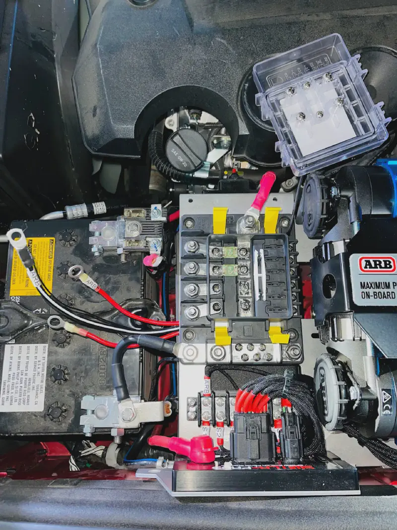
Getting everything arranged is quite a challenge. Especially with the larger gauge wires.
Add-a-Fuse Circuit Tap
Moving on to the cabin wiring, I wanted to specifically include a section in this guide for the correct add-a-fuse orientation. I have seen many examples of incorrect orientation, which defeats the entire purpose of fuses and exposes you and your vehicle to increased chance of electrical fault. Without the benefit of a fuse the electrical current can flow unchecked and can burn up wires or at worst, start a fire. This risk is exponentially more than the average car owner since the off-roading community commonly exposes our vehicles to some of the harshest environmental conditions available. A great way to learn more is with this Add a Fuse Video Guide that I have re-watched many times in order to get installations correct and safe. The video is full of relevant information for this install and correctly instructed me that my 2021 4Runner uses a low profile mini fuse (in the cabin box), how to chose a fuse to piggyback off, the correct orientation for my add-a-fuse, and most importantly of all, how to determine the hot and cold aisle for an automotive fuse box.
The most helpful first step would be to determine what kind of fuse type your vehicle is using. It could be anything from ATC/ATO, ATM mini, Micro2, or a Low Profile Mini. Knowing what type you have will make ordering or picking up the correct add-a-fuse kit that much easier. I was in a rush when I grabbed mine from the local AutoZone and got the incorrect size (ATM Mini). While it connects just fine, the spacing is tight and in the future I will have to cut it out in order to add the correct size so it fits much better. You can see in the very last image of this article my semi-bent add-a-fuse in the top left of the image. The size is a bit too much and it rubs up against a metal sheet underneath the steering wheel.
The next step would be to review your available fuses and tap a non-critical service. Alternatively, if there are any open fuse slots they should be used first before leeching off another. In my case I had an empty fuse slot I tried to use for the SP-9100 Blue wire (ignition) but it was always powered, which is what I didn’t want. So I had to move on to another fuse in order to get the correct type. You should absolutely not tap any fuses labelled with critical services such as ABS, brakes, air bags, cooling, engine control modules and other mechanisms that are critical to the operation of the vehicle. After testing and validating a few locations in my own fuse box I ended up tapping the 10A tail lights for the SP-9100 white wire (light dimming trigger) and the 10A KDSS for the blue wire (ignition). While KDSS is incredible critical, my 4Runner actually doesn’t have it and so should be completely fine to tap.
Cutting a Fuse in Half
The methodology for selecting my fuse tap locations can be demonstrated in the previously linked video. The basic summary is to find the type of power going to a fuse and thereafter identifying the positive and negative side of the rail. Your car’s electronics are powered by three separate types of power. The first is switched power that is provided when the vehicle is actually running the engine. The second is switched (RAP) and is powered when the ignition is engaged by the engine isn’t running and turn off after you open the door or a certain amount of time elapses. Think of something like your car radio or overhead lights that turn on after turning off your engine and remain on for maybe a minute or two or until you open a door. The third type is unswitched where power is supplied all the time. In order to figure out what fuses are provided by these types of power you need to cut a fuse in half.
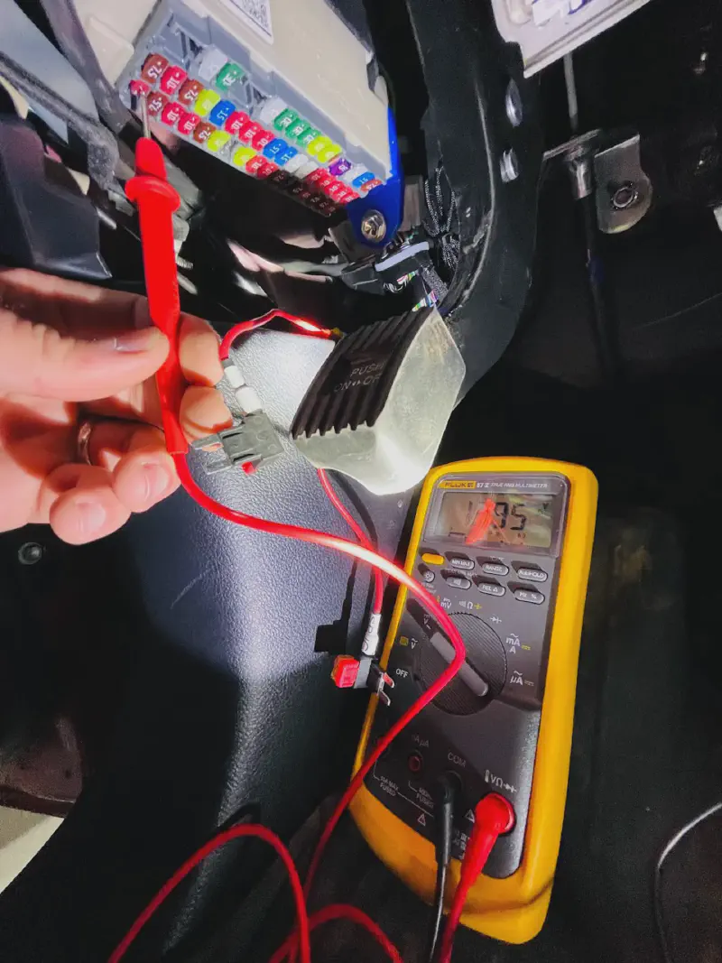
Fuse testing
Cutting a fuse in half will give you a simple tool that can tell you if either side of fuse is energized or not. Fair warning that you will need a multimeter to help out here. Be aware that each fuse rail will have a negative side that will show no electrical charge in any state. If you see that behavior just keep a note of it since it is important later for correctly orientating the add-a-fuse tap. By taking this mangled fuse and plugging it into each fuse rail while the engine is completely off we can identify which fuses have unswitched power. For this application you don’t want to use those because it will needlessly drain your power when the vehicle is off. Further isolation with the ignition enabled but the engine still off can show us the switched (RAP) powered fuses. Lastly, with the engine running we can see which fuses are powered by purely switched power.
Tap orientation
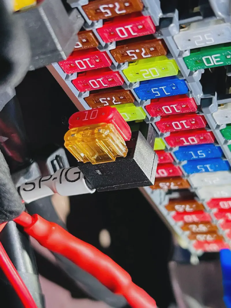
Tap orientation is important
If during the course of your testing you found that some sides of fuses were completely dead you can use this critical information to correctly orient your add-a-fuse circuit taps. The internal circuity of an add-a-fuse requires that the prong on the opposite side of the wire is energized while the prong on the closer side is connected to your negative. If the add-a-fuse is plugged in backwards you essentially lose the protection of the fuse. In a previous image you can see me testing with a multimeter with a fuse cut in half. The output of 13.95V on the right hand side rail demonstrates that it is energized. Based on that information we can safely orient the add-a-fuse with the cable exiting the left side as shown in the above image.
Wiring Gauge
All of the wiring is already supplied from the products purchased for this project but if you want a head start on wiring new accessories it would be helpful to know what size (gauge) wire you need. The company Blue Sea Systems has a great chart outlining the needs for wire gauge based on distance and amperage. Since the American automotive DC voltage standard is 12.8V we are subject to making up the difference with high amperage draw to get anything of substance running.
Problems, Workarounds, and Suggestions
Every project in almost any hobby has a balancing act of convenience, cost, and intention. The electrical foundation I have built is no different. There will be times in the future where I question my own judgement on selecting certain components and also deriding the architecture of product designers as I become more proficient with my gear. To save you the several year wait before I become enlightened I will make a few critiques of the entire setup. Hopefully this helps people going down the same path from needless frustration or some missing piece of information.
Location
The engine bay near the starter battery is without a doubt the absolute best location for this assortment of gear. You have close access to wiring into the driver’s side cabin and high amperage wires only have to run a short distance to the main battery. Perhaps the biggest issue in the future will be access to the engine bay relay and fuse boxes. I been trying to avoid thinking about how much of a pain it will be to at first diagnose and thereafter fix any electrical issues that originate in those boxes. Lets take an example of some electrical issue in your vehicle. Instead of easily checking the vehicle’s main fuse box you will probably end up trying to identify the issue elsewhere because the time involved to remove the mount tray is considerable. Thus we have entirely erased decades of improving electrical troubleshooting efficiency by ignoring all these connections that were routed to a central location. The painful removal process for the mount tray isn’t any fault of its own. By itself it would be incredibly easy to unscrew 4 bolts. But the inherent nature of its purpose in bringing tons of wires together makes it a statically wired feature of your vehicle’s engine bay. When running wire for new accessories I trim everything to a neat fit-to-length amount. This might ultimately backfire when the pretty cabling becomes the main crux of getting access to the underlying relay and fuse box.
Layout and Orientation
Another critique is the layout of the SD Offroad Mount Tray itself. There are many different styles of the mount and the respective arrangement of components. But for mine it felt cramped between the SP-9100, bus bar, and the SafetyHub 150 fuse block. To accommodate everything together involved a lot of cursing and finger mashing. The first aspect of this problem is the incredibly small space and orientation between the vertical SP-9100 and the horizontal bus bar. Realistically, you want the left side of the bus bar available since it is closest to the gap used for wiring cables. That only leaves the right hand side to wire up the SP-9100 at an insane angle. No matter how you wire the SP-9100 to the bus bar you will inevitably block the bus bar from above. I am not looking forward to the time when I try to plug in switches 5-8 as they are behind the fat wad of SP-9100 cables.
In addition, the space between the bus bar and the fuse block is much too small. I would like to see more room on the fuse block side since it will get a lot more use than the SP-9100 bus bar. Pushing the fuse block mount location an inch to the left and expanding that cable access hole would ease a lot of my worries about the physical ease of installing, diagnosing, or removing connections from the fuse block.
I’m currently designing a 4 cell 3,584 amp hour lithium iron phosphate battery bank complete with an inverter, AC power supply, and MPPT. Its going to look like a Mad Max-like dumpster fire but will perform better than most consumer models generally available. ↩︎
“Should I use a Fuse Block for my output wires? No – connecting our output wires to a fuse block subjects the wires to water and corrosion, and essentially takes our Solid State, watertight system, and makes it subject to potential water damage and unreliable connections. It also adds unnecessary expense. We suggest using the heat-shrinkable butt splices (included in the installation hardware kit) OR soldering (and covering with heat shrink tubing) the power leads together.” Switch-Pros Frequently Asked Questions ↩︎
“Do I need to add Relays and/or Fuses? No – for installation of basic lights and electronics, you may connect the power leads directly to one another by soldering or using heat-shrinkable butt splices. Exceptions: if you are connecting loads that will exceed 85% of the circuit’s capacity OR if you are connecting accessories with inductive loads (compressors, pumps, large fans), then you SHOULD put a relay in line.” Switch-Pros Frequently Asked Questions ↩︎
“Just installed ARB twin on SDHQ mount wired to sp9100 two days ago. I scrapped the provided harness and made my own with CE electric 8AWG wire. Independent positives with maxi fuses, and combined ground wire including the small 20AWG wire to simplify things. The switch harness from ARB is a joke. Chop everything off except the purple wire, which is run to your switch pros. The wire was a little short for the routing I chose so I had to splice in an extension with some of the previously scrapped wire. I just snipped and sealed the other ground wire coming from the switch.” ARB Twin Compressor Install WITH Switch Pro SP9100 ↩︎